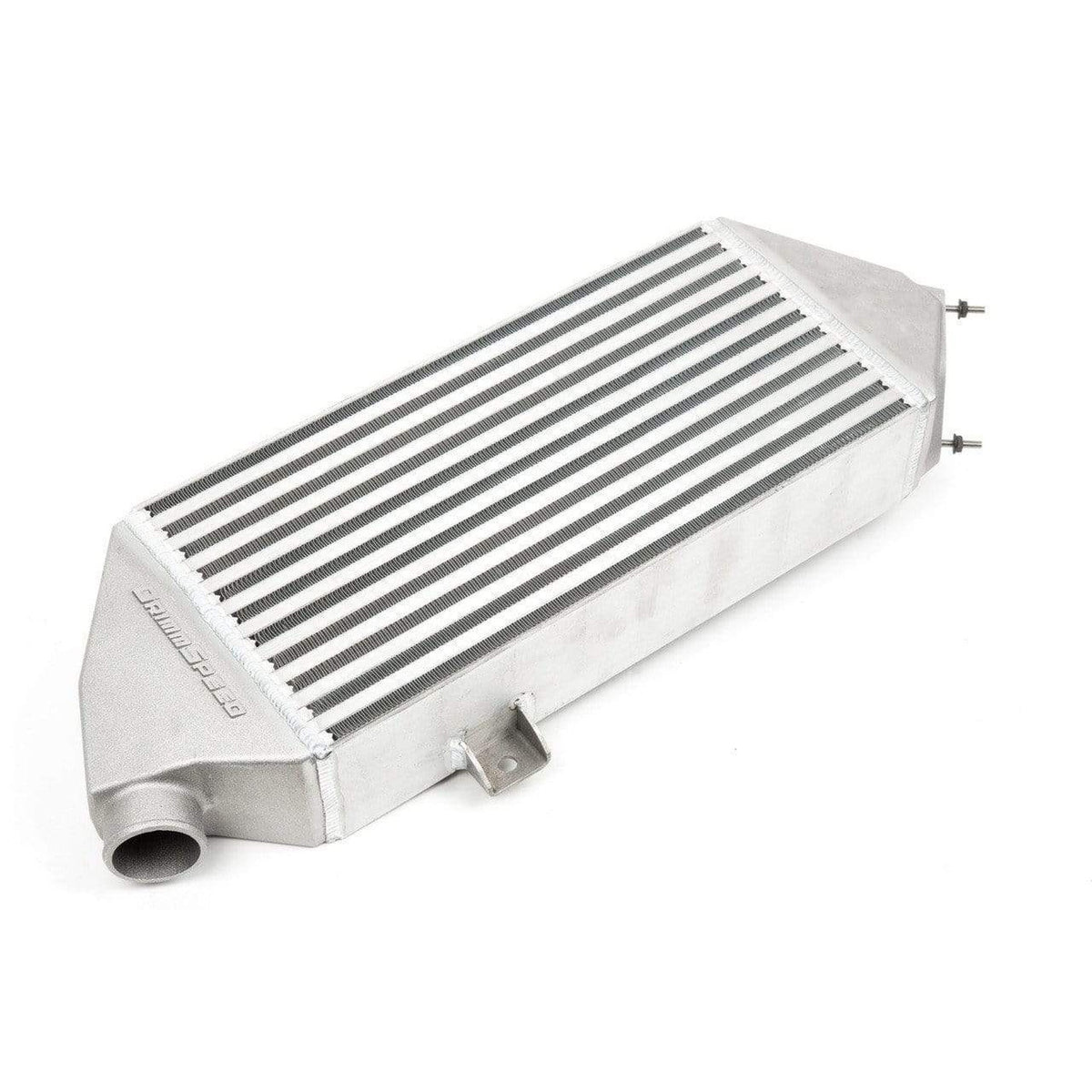
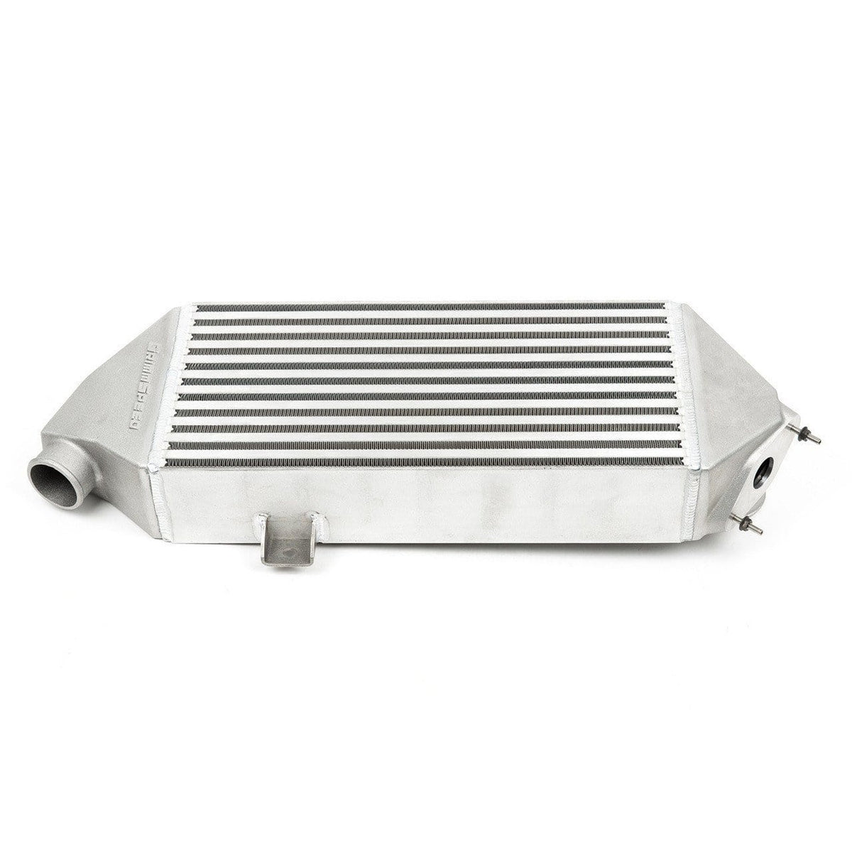
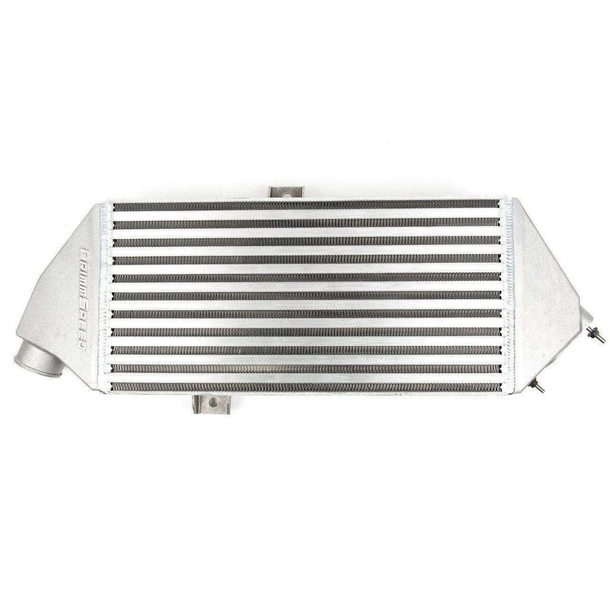
GrimmSpeed Silver Top Mount Intercooler Subaru Legacy GT 2005-2009 GrimmSpeed
$ 999,00 $ 249,75
You probably already know that you want an intercooler with maximum cooling and minimum restriction, but when it comes to selecting the right ‘man for the job’, we think it’s important to understand why. As air is pressurized by your turbo, it heats up, not because of the heat of the turbocharger, but because when they’re compressed, the atoms in the air are forced closer together and as a result, move faster and have more energy. That energy manifests itself as heat. The more heat we can remove from the system, the denser the air becomes and that’s what helps eliminate pre-detonation, or ‘knock’, allowing for increased output from your system. Your OEM TMIC does just fine at stock boost under normal use, but as soon as you start putting some real heat into it with higher boost or harder use, it heat-soaks beyond recovery.
Part #: 090027
Quick Specs:
- 17.5in x 8.7in x 3.5in Cross Flow Core – careful balance of high heat transfer and low pressure drop
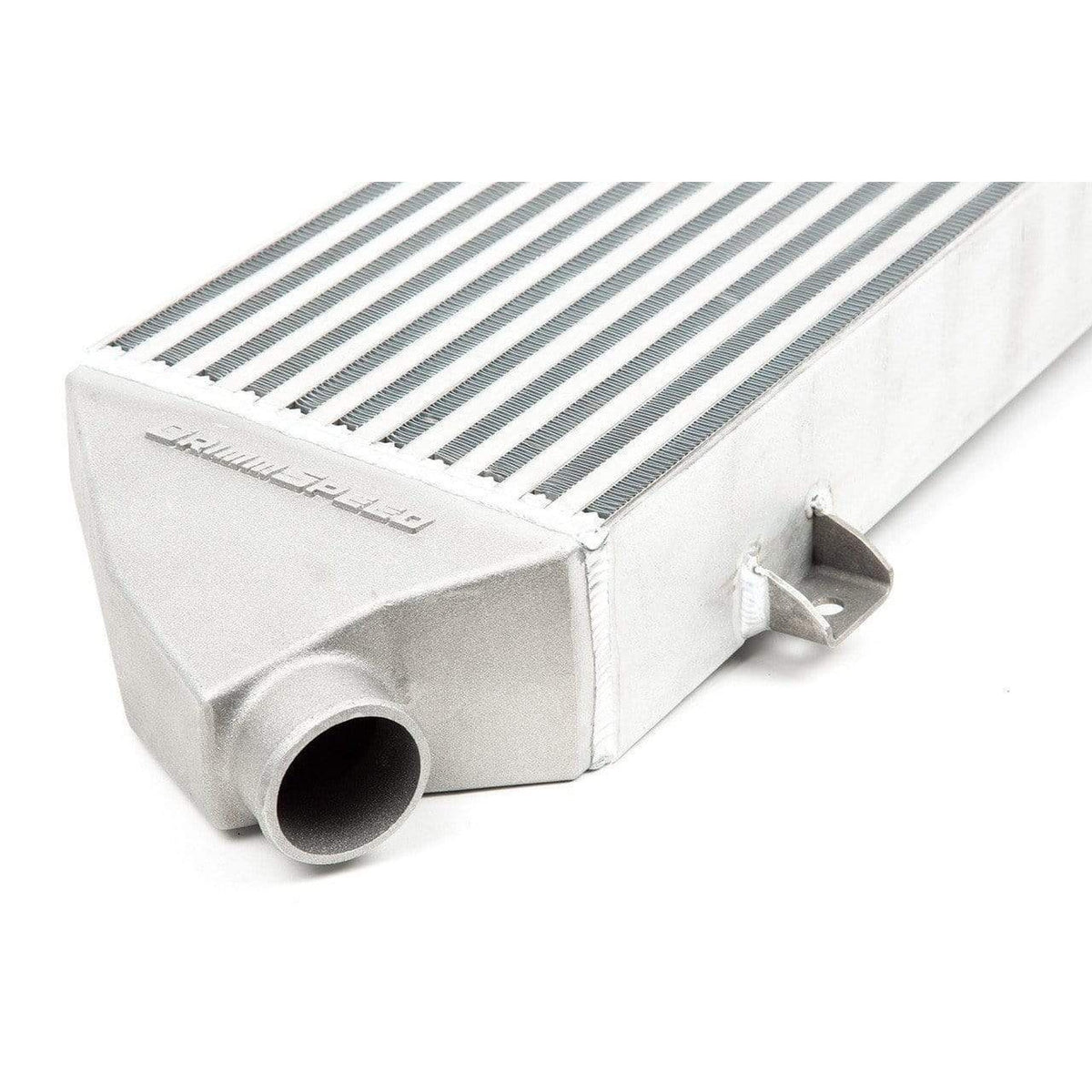
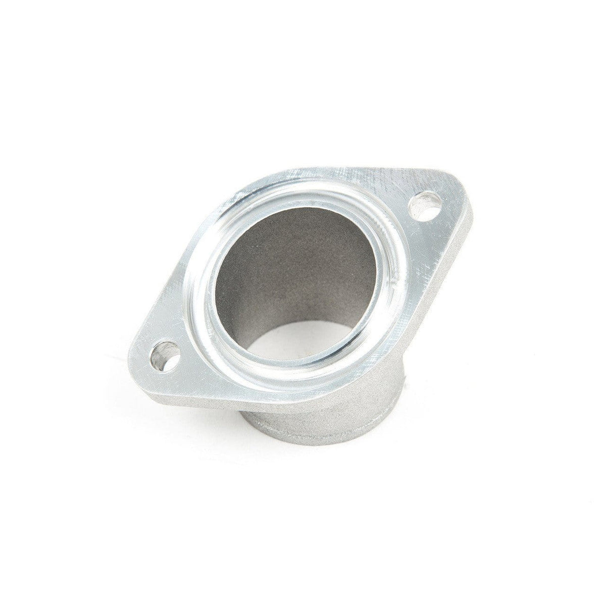
- Cast Aluminum End Tanks – machined BPV flange for precision fit and perfect seal
- 5-Ply Silicone Couplers – custom molded and reinforced for demanding environments
- Wide-Mouth Splitter – collects air from the entire width of the scoop
- Vibration Isolation Mounting – keep the intercooler system from fatigue due to vibration
- Stainless Steel BPV Studs – avoid the risk of damaging fragile aluminum threads
- Cleaned, Inspected and Sealed Prior to Shipping – prevent motor damage due to foreign matter
Design:
There are two primary considerations in the design of an intercooler: maximum heat transfer and minimum pressure drop. Unfortunately, one causes the other, so finding a perfect balance requires a detailed understanding of the intended application, some serious engineering power and the highest quality manufacturing processes. Fitment and quality are also critically important to ensure that the most safety-critical part of your turbo system is up to the task every time your foot hits the floor. We began by laser scanning an OEM TMIC to plot the mounting points and space claim in CAD with pinpoint accuracy. At the same time, we designed a custom bar and plate core with overall dimensions, fin density and fin types that would provide the insane heat transfer area we require with minimal flow restriction. With core size nailed down, we got to work designing end tanks that offered smooth flow, perfect fitment and even distribution of the hot charge air through the core. Countless revisions were tested in flow simulation before we finally found exactly the characteristics that we wanted. From there, 3D printed prototypes were used to confirm fitment and we began work on manufacturing details in preparation for verification testing and production.
Construction:
Each intercooler uses two unique end tanks. The first accepts the hot charge air from the turbo and feeds it to the intercooler core. The second receives the cooled charge air from the core and delivers it to the throttle body. These end tanks are precision cast and machined right here in Minnesota. The bypass valve flange is milled flat and stainless steel studs are permanently installed to ensure that the aluminum threads don’t become damaged and shorten the life of the intercooler. Following inspection, end tanks are welded to high density bar and plate intercoolers before the entire assembly is pressure tested, cleaned and sealed for shipment. 5-ply silicone couplers hold their shape in extreme conditions and ensure that charge air makes it to and from the intercooler with no trouble. Splitters are laser cut from aluminum sheet and CNC bent before being assembled and powdercoated with a durable texture black finish. Stainless steel hardware secures the splitter to the factory hood scoop.
Prompt Delivery and Professional Packaging
Thanks to our longstanding association with UPS FedEx DHL, and other leading international carriers, we are able to provide various shipping options. Our warehouse personnel are well trained and will be able to pack your goods in accordance with the exact and precise specifications. Your goods will undergo an exhaustive examination before they will be properly packaged prior to being shipped. We deliver to thousands of customers every day from all over the world. The fact that we are dedicated to becoming the largest online retailer in the World is clear. These warehouses are situated in Europe just as they are in the USA.
Note: Orders that contain more than one product are assigned a specific processing time depending on the specific product.
We will inspect each and every one of the items ordered before shipping. Most orders are delivered within 48 hours. The delivery time will be between 3-7 working days.
Returns
Stock is dynamic, and not fully managed by us due to the involvement of multiple different parties, such as the factory and our warehouse. Actual stock levels may fluctuate at any time. Be aware that your order may be out of stock once the order is placed.
Our policy is valid for 30 days. We cannot exchange or refund your order if it has been 30 days from the date of purchase.
The item must not be used and in its original condition. It must also be returned in its original packaging.
Related products
Exterior Fenders
ABW Motorsport 60mm Fender Flares Arch One Piece Subaru WRX Sedan 2002-2003 ABW Motorsport
Exterior Fenders
ABW Motorsport 40mm Fender Flares Recessed Two Piece Subaru WRX / STI 2004-2005 Sedan ABW Motorsport
Exterior Fenders
ABW Motorsport 40mm Fender Flares Recessed One Piece Subaru WRX 2002-2003 Sedan ABW Motorsport
Exterior Fenders
ABW Motorsport 60mm Fender Flares Recessed One Piece Subaru WRX / STI Sedan 2004-2005 ABW Motorsport
Exterior Fenders
ABW Motorsport 80mm Recessed Arch Fender Flares Subaru WRX / STI 2002-2005 Sedan ABW Motorsport
Exterior Fenders
ABW Motorsport 60mm Fender Flares Arch One Piece Subaru WRX / STI 2004-2005 Sedan ABW Motorsport
Exterior Body Kit
ABW Motorsport 4 Door to 2 Door Conversion Rear Quarters Subaru WRX / STI 2002-2007 ABW Motorsport
Exterior Fenders
ABW Motorsport 60mm Fender Flares Arch One Piece Subaru WRX / STI 2006-2007 Sedan ABW Motorsport
Interior Floor Mats
3D MAXpider 2018-2019 Tesla Model 3 Elegant 1st & 2nd Row Floormats – Black 3D MAXpider
Exterior Fenders
ABW Motorsport 40mm Fender Flares Two Piece Subaru WRX / STI 2006-2007 Sedan ABW Motorsport
Interior Floor Mats
3D MAXpider 2020-2021 Tesla Model 3 Elitect 1st & 2nd Row Floormats – Black 3D MAXpider
Interior Floor Mats
3D Maxpider Heavy Duty All Weather Floor Mats Subaru Impreza 17-22 / Crosstrek 18-22 3D MAXpider
Exterior Fenders
ABW Motorsport 60mm Fender Flares Recessed Two Piece Subaru WRX Sedan 2002-2003 ABW Motorsport
Interior Floor Mats
3D MAXpider 2012-2020 Tesla Model S Kagu 2nd Row Floormats – Black 3D MAXpider
Exterior Fenders
ABW Motorsport 40mm Fender Flares Arch One Piece Subaru WRX / STI 2006-2007 Sedan ABW Motorsport
Exterior Fenders
ABW Motorsport 60mm Fender Flares Arch Two Piece Subaru WRX / STI 2004-2005 Sedan ABW Motorsport
Engine Power Packages
Exterior Fenders
ABW Motorsport 60mm Fender Flares Arch Two Piece Subaru WRX / STI 2006-2007 Sedan ABW Motorsport
Exterior Fenders
ABW Motorsport 40mm Fender Flares Arch One Piece Subaru WRX 2002-2003 Sedan ABW Motorsport
Exterior Fenders
ABW Motorsport 60mm Fender Flares Recessed One Piece Subaru WRX Sedan 2002-2003 ABW Motorsport
Exterior Fenders
Interior Floor Mats
3D MAXpider 2012-2014 Tesla Model S Kagu 1st Row Floormat – Gray 3D MAXpider
Exterior Fenders
ABW Motorsport 60mm Fender Flares Recessed Two Piece Subaru WRX / STI Sedan 2004-2005 ABW Motorsport
Exterior Body Kit
ABW Motorsport 4 Door to 2 Door Conversion Kit Subaru WRX / STI 2002-2007 ABW Motorsport
Exterior Fenders
ABW Motorsport 40mm Fender Flares Recessed Two Piece Subaru WRX 2002-2003 Sedan ABW Motorsport
Exhaust Axle Back
